
Arc flash is a sudden, explosive release of energy from an...
Read
This content was produced in December of 2018. A paper version copy can be downloaded from here.
Abstract— This paper, which is based entirely on the review of bibliographical and scientific publications, explains several aspects commonly found in the research of Hybrid Energy Storage Systems (HESS) based on Lithium-ion (Li-ion) batteries and ultracapacitor technologies. Basic characteristics of both technologies, their modeling and design in HESS contexts are explained, as well as important parameters often used to measure their states. Next, an explanation of common power electronic topologies in HESS applications is developed, along with some typical design considerations as explained in the literature. Finally, approaches in the Energy Management Systems of HESS are explained, along with some relevant examples and outcomes.
I. Introduction
During the last decades, the development of Electric Vehicle (EV) technologies has triggered an irreversible change in the way humanity approaches ground transportation, from a highly contaminating and inefficient one, to the more efficient and environmentally friendly electrical one. Even though there are still few years until electrically based ground transportation becomes predominant, there is no question the departure from combustion fleets will take less than one generation.
Among all technologies and challenges associated with EVs, one of the most relevant and impacting ones is the on-board energy source. Available options having the potential of practical application in mass scale cannot fulfill, individually, fundamental characteristics of an ideal energy source: high energy density, high power density, low cost, ability to charge and regenerate fast, and range comparable with that of Internal Combustion Engine (ICE) vehicles [1]. Hence, combining them in what is called Hybrid Energy Storage Systems (HESS), is necessary for EV applications [2] [3] [4].
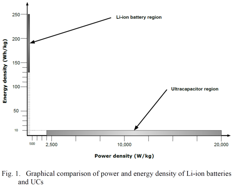
There are four viable energy source options for EV application: batteries, ultracapacitors (UC), flywheels and fuel cells; but mostly the former two are promissory in the foreseeable future from the technical, financial and / or safety standpoints. Batteries, which offer high energy and low power densities, are the most mature technology, and will continue to be the predominant energy source for EV applications, particularly the Lithium-ion (Li-ion) type. Ultracapacitors, on the other hand, show exceptionally high power density, but lack energy density, and present high initial cost [2]. Fig. 1. indicates, in more specific terms, how power and energy density compare in these two energy sources, according to [3], [4] and [5]. It is important to notice that ranges correspond to different brands and variances and that, according to [5], energy density in UCs could increase by a factor of 10 or more in the near future.
The combination of these two energy sources, which complement each other in a single HESS, has been the subject of numerous research studies around the world in recent years. In addition to the HESS per se, research has also been intensive in how to optimally implement the two coexisting sources on board EVs [3] [6] [7] [8]. This implementation usually comprises three aspects: the sizing of batteries and UCs, the means to convert voltages between components of the system (batteries, ultracapacitors, inverters and motors), which pertains different topologies of power electronics converters, and the way to control and distribute power exchanges between such components.
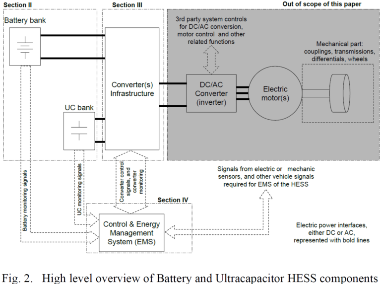
This paper reviews some of the latest trends on HESS research for EV applications. It is divided as follows: Section II presents concepts and design criteria for batteries and UCs. Section III shows power converters, topologies, and design for HESS applications. Section IV presents energy management systems, and Section V discusses about future research and challenges. Fig. 2 shows the components of HESS that this paper discusses [9] [10] [11], with Sections of the paper that correspond to each item.
II. Batteries and ultracapacitors
A. Basic Concepts
1) Batteries.
Storing energy in an electrochemical way, batteries are a well established technology and the most prevalent source in EV applications. Although several types like nickel, lead and zinc based have been in use for decades, research is strongly focused on improving what the scientific community considers the most promissory due to its performance: the Li-ion type [2].
Although enjoying high popularity in applications and research for high performance EVs due to their high energy density, high voltage, low self-discharge and mass, wide temperature range, and low memory effect [12] [13], Li-ion batteries are notorious for lacking power density, in addition to their vulnerability to operating temperature, high power or too frequent charging/discharging cycles, which threaten their lifespan [4] [6] [9] [14] [15]. Due to this, when used alone they must be oversized, adding to their already high initial cost [4] [6] [16], which is in the range of 600 to 1000 USD/kWh [2]. Therefore, limiting sudden or high charge and discharge currents of the batteries, and instead keeping their utilization as smooth and limited as possible by controlling its power delivery, their temperature rise or keeping their State of Charge (SOC, explained next) or its rate change within certain ranges, are among the main goals of majority of HESS research [1] [4] [7] [14] [15].
Li-ion batteries are also said to have a lifespan of 500 cycles of 80% charge. The usual criteria for the end of life (EOL) of a battery is when the energy capacity of the battery has been degraded by 20% or more [6] [10] [12] [15].
Capacity degradation models for Li-ion batteries are experimentally determined, and are expressed as follows, according to [6] [10] [15]:

Where ΔQloss is the battery degradation (in percentage), T is the absolute temperature, R is the gas constant, Qtp is the charge throughput, or total charge in Amp-hour (Ah) that goes through the battery up to the moment of the calculation, z is a defined factor of 0.55, and B and Ea are parameters that depend on the battery C-rate, which is defined as the rate at which a battery is discharged regarding its maximum capacity [17].
State of Health (SOH) is, on the other hand, another important parameter often included as a factor in HESS systems research. Simply put, SOH is a percentual estimation of a battery’s ability to store and release energy (give or take high currents, and retain charge over long periods [12]), as compared to a brand new battery [18], or a measure of lifetime gauge [13]. The variation of SOH relates with (1) as expressed in equation (2) [10], assuming ΔQloss as 20% (accepted criteria for battery EOL). The equation is a practical mean to estimate SOH in real time and realistic driving conditions for the purpose of research, with the limitation that temperature and battery age are not considered:
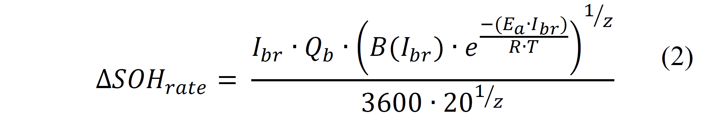
Where Ibr is defined as the rate of the battery current versus its nominal Ah capacity, Qb. All other parameter already defined above.
Finally, another battery quantity usually found in research as an important dynamic indication of the battery’s current charge (Ah), in percentage of its rated capacity [12] [18], is the State of Charge (SOC). There are several ways to estimate SOC in batteries, and very complex research has been performed in this particular aspect, but the Coulomb or ampere-hour counting method, despite presenting drawbacks like error accumulation, is by far the most commonly found in research of HESS implementation due to its simplicity [12] [13] [19] [20]. In its most basic form, Coulomb based SOC of the battery is obtained by a current integration as follows [1]:

Where SOCinitial represents the SOC at an initial point of the calculation, t0 ant t1 represent the times considered in the integration, and iBat is the instantaneous battery current. Other research like [9] and [15] have used small variations of the current integration shown in (3) for SOC calculation.
2) Ultracapacitors.
Considered also a promissory energy source and a common appearance, along with batteries in HESS research, UCs fill some of the most important lacks Li-ion batteries have, as shown in Fig. 1. Specifically, UCs present exceptionally high power density and, for all practical purposes and as opposed to batteries, unlimited cycles and service life [2] [5] [6] [15]. On the downside, in addition to a low capacity to accumulate energy per volume and mass, supercapacitors are still an expensive technology, with a price 2400 – 6000 USD/kWh, four to ten times the case of batteries, and more difficult to control due to their non linear voltage to current characteristics, and frequency [2] [5].
It is important to distinguish terminologies and types. UCs, in general, refer to the overall technology of using capacitances to store electrical energy. UCs have different variances like High Voltage Ceramic Capacitors, Electric Double Layer Capacitors (EDLC), and pseudo capacitors. Even though EDLCs are a type of electrochemical capacitor, they are indeed electrostatic energy storage devices, (electro chemistry occurs in the EDLC process, but the actual energy storage is entirely electrical, no chemical reactions). On the other hand, pseudo capacitors function in a way very similar to rechargeable electrochemical batteries. In literature and research, the terms EDLC and UC are sometimes used interchangeably [5].
As in the case of batteries, a quantity that is usually referred to and used in HESS research is the SOC of the UC (SOCUC) [6] [7] [9] [14] [21]. As in the case of batteries, the quantity refers to the rate between actual charge (Coulombs) to nominal charge in the UC [9]. Departing from basic relationships of capacitance and voltage, the basic definition of SOC, [6] and [9] define SOCUC as follows:

Where V(t) is the instantaneous voltage in the UC, and Vnominal its nominal voltage. Given that the simplest UC model is more than just a single capacitance (to be explained below), it is reasonable to assume that equation (4) presents inaccuracies. A definition of SOCUC like the one presented in (3) is used in [15]. The control of SOCUC could be in certain cases like [7] and [15] the goal of the control of the HESS.
B. Modeling
1) Batteries.
Literature is crowded with approaches to battery modeling [20] [22] [23] [24] [25]. The approach to use is highly dependent on the purpose, and they could be electrochemically, mathematically or electrically oriented. For example, a model that fits the purpose of battery design, might be computationally heavy for EV applications [22]. There is, however, consensus on the four types of battery models for most electrical environments: the Rint, Thevenin, RC, and PNGV models [20], each of which showing merits and drawbacks. Fig. 3 shows the configuration of each model according to [25], with Ux, Rx and Cx being arbitrary DC voltages, resistances and capacitances that adopt different names and values depending on the model.
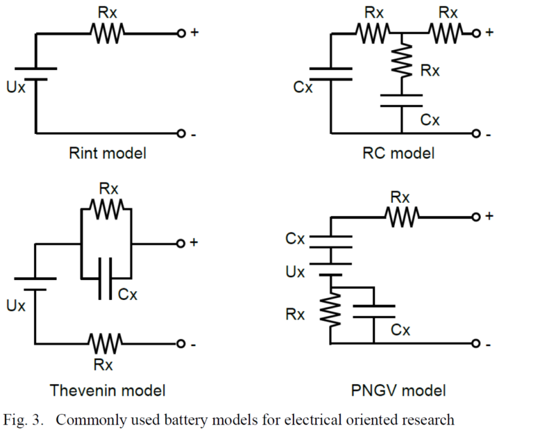
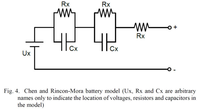
When it comes to the specifics of HESS research, there is two major tendencies in the use of battery models: those cases in which the nature of the study allows simplicity tend to use the models showing in Fig. 3 [6] [16] [26] [27]. However, other cases in which a more detailed model is required when, for example non linearities, temperature, cycle number, etc. must be accounted for, use the Chen and Rincon-Mora [28] model shown in Fig. 4, or some variation of such model [1] [9] [10] [29]. Another specific battery model is used in [4], from [22].
2) Ultracapacitors.
The biggest challenge when it comes to study the applicability of UCs is its modeling. This is because their construction and material characteristics made their parameters non-linear, and dependent on characteristics like voltage and temperature. Such non linearities can be directly observed in explicit curves presented in [5] [30] [31].
As in the case of batteries, authors have proposed an abundance of modeling approaches for UCs over the years [5] [30] [31] [32] [33]. Similarly, selecting one type of model over the other depends on the application and use, keeping in mind that the more accurate the model, the more computationally expensive, while simplified models tend to be appropriate for application research, at the expense of accuracy [31]. Fig 5. shows UC models commonly found in electrical system level studies [5] [30] [31] [32] [33].
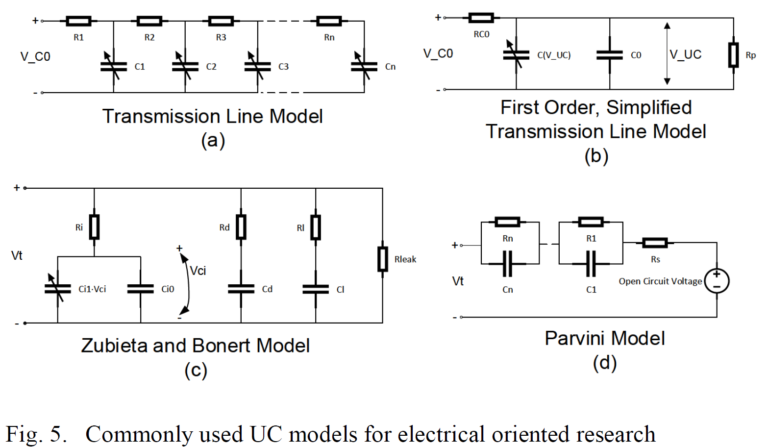
One model commonly cited in research before the last decade is the one by Zubieta and Bonert. The model indicates few RC branches connected in parallel between the terminals of the UC, as indicated in Fig. 5 (c). Each branch corresponds to a phenomena or time constant of the internal dynamics of the UC. Most of the models use similar philosophies. It can also be observed that most models show considerable non-linearities and variable interdependency.
Research specific to HESS applications can range from the use of very simplistic series RC circuits like in [6], or the one presented in [9], which removes the voltage dependency of the variable capacitor in Fig. 5 (b), to others that resemble the Zubieta and Bonert model with simplifications, some of them presented in [33], by either ignoring the voltage dependence of the capacitor [1] [26], or by removing the less impacting RC branches [27] [34]. Other research like [10] and [16] use simple series RC circuits, but with variable parameters obtained from lookup tables, while [34] obtains the fixed parameter of its model from experimental results.
C. Design, Sizing and Optimization
Batteries or UCs, when considered by the unit, are hardly ever suited for direct connection in practical high power cases, and therefore must be arranged in parallel connected strings of series connected units. Such arrangements are usually referred to as banks, and each individual unit of the bank is called a cell.
In general, design and sizing of batteries and UCs banks for EV applications are driven by three main factors: the DC voltage to which each bank will be connected (Volts), the amount of energy desired to be available (kWh), and the power delivery limitation and/or losses of each cell in the bank (kW or current), when compared to the total power needs. The DC voltage factor determines the amount of series connected cells, while the other two factors (energy and power), drive the number of parallel connected strings [5] [6] [10] [16] [21] [34] [27].
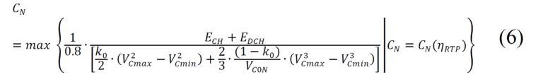
Author [5] develops a very comprehensive methodology to calculate voltage and capacitance of UC banks, considering the simplified model Fig. 5 (b). In summary, equations (5) and (6) determine voltage range and capacitance:

In equation (5) PUC_out is the power required from the UC, RCO (ESR) is the UC resistance in Fig. 5 (b), IUC_max is the maximum current allowed at the output of the UC, ICO is the actual operating current, VUC_range is the voltage design range and Vconverter_input is the rated voltage in the converter or device to which the UC will be connected.
Other aspects like life span, and expected intermediate voltage, could influence the outcomes of equation (5) for a final determination of the rated voltage of the UC cells and bank. Also, thermal management and voltage balancing networks between cells are part of the design steps explained in [5].
In equation (6), which determines the nominal capacitance of the bank, k0 represents the normalized initial capacitance, VCmax and VCmin are the maximum and minimum internal voltage of the UC, VC0N is the nominal voltage, ECH and EDCH are the charge and discharge energy, and CN(ηRTP) is the nominal capacitance as a function of what [5] defines as “roundtrip efficiency”. This equation considers advanced factors like EOL, charge and discharge behavior, and conversion efficiency.
In other cases, design criteria of the EMS could influence further the number of cells in the UC bank, like in [9]. In there, the UC bank is established by principle as a “power buffer” as opposed to the main energy source of the EV, and therefore it is arbitrarily decided that 50% of the energy of the UC bank should cover the largest power peak expected in the study. On the other hand, cases like [35] arbitrarily selects the UC bank voltage same as the battery bank, despite using power electronics allowing other voltage choices. Additionally, [8] indicates that the working voltage of the UCs are usually ranged between 50% and 100% of the DC value, which is the case in [36].
It is important to notice that, due to the nature of each energy source, with the UCs having a quadratic relationship between energy and voltage, which results in a wide range of terminal voltage [5], while the batteries present a rather fixed terminal voltage over a wide range of current [16], along with the type of converters between them and the load (Converter Infrastructure in Fig. 1), the voltage design is highly influenced by the power electronics topology to use [5]. For example, all cases of UC and battery banks in [4] are designed around the studied power electronics options. Converter infrastructure topologies will be addressed in Section III.
Finally, optimization of energy sources is highly dependent on the type of Energy Management System (EMS) and power split to be used in the HESS. Optimization details, which could or could not include the sizing of the battery and/or UC banks, are addressed in Section IV.
III. Power converters and their combinations in battery and ultracapacitor based HESS
A. Basic DC DC topologies
HESS interface with their supported machinery (DC machines or AC machines) via power converters that have DC voltage as their inputs, in majority of cases. Considering batteries and UC are DC voltage energy storage devices, it is reasonable to see that HESS research revolves around DC-DC power converters.
Traditionally, there are 4 types of DC-DC converters: step-down or buck, step-up or boost, buck-boost, and Cúk. The main differences between them are the relationship they can carry between the output voltage versus the input, either introducing a reduction (buck), an increase (boost), or both (buck-boost and Cúk), by manipulating the duty cycles of their switching pairs. Also, there are differentiations in their bi-directional abilities. Authors [2] and [37] elaborate plenty on their details and constructions. Other type of DC converters like diode bypass buck-boost, dual and active cascaded buck-boost are referred in [14].
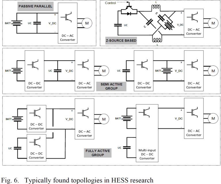
A relatively new variance of the traditional DC-DC converters, that has found significant attention in EV applications, is the Z-source converter. It was presented in 2003 by [38]. Essentially, it introduces a “X” shaped network of two diagonal capacitors and two straight inductors (see Fig. 6) between any combination of DC to/from AC or DC to/from DC converters. It allows for tremendous flexibility in features in which traditional DC-DC converters present limitations.
Particularly in the case of HESS research, and as indicated in [8], Z-source allows for a merge between the HESS system and the motor inverter, at the time it provides buck boost capability and improved reliability, less complexity, less costs and improved controllability, as the motor and both the battery and the UC can be controlled simultaneously.
B. Typical Combinations for HESS
Research like [4], [6], [8] and [14] make reference to the typical combinations in which battery banks, UC banks and their corresponding loads can be interfaced with power converters in HESS design. Fig. 6 shows such commonly found topologies.
In Fig. 6, the passive topology is the simplest and less expensive, but at the same time the most disregarded in research due to its very limited controllability, which underuses the UC and tends to damage the battery bank [3] [4] [36]. The Z-source based topology is the one presented in [8]. An interesting and complex configuration, the battery bank is connected in parallel with one of the two capacitors of the impedance network, making the power converter of asymmetric operation. On the other hand, [11] presents a power converter configuration that is a reduced version of a Z-source, called quasi-Z-source, which has also found attention in recent research.
Also, in Fig. 6 there is the semi active group, which is among the most common appearances in HESS work, and the best option according to [3] and [6]. Specifically, the one on the left is called “battery semiactive”, while the one on the right is the “capacitor semiactive”. It works by making one of the two energy sources of the HESS controllable, by means of the interposed DC-DC converter, which adds significant benefits and flexibility. Within the two options, and according to [4], advantages and disadvantages are hard to delimitate, as for example, the capacitor semiactive topology is more efficient and minimized temperature rise in the battery, but at the same time more complicated and sensitive to load dynamics than the battery semiactive. On the other hand, the battery semiactive topology shows higher efficiency before highly dynamic loads, but such efficiency is also dependent on the efficiency of the DC-DC converter used. Reference [4] provides a well developed study on this matter.
The capacitor semiactive topology is the one selected by [16] and [36], the latest claiming it is the most prevalent in HESS research, as it allows range for the UC voltage, while giving stability to the battery [6]. Literature, as can be seem, is not consistent about which one is the best option, probably because there is no single answer that fits the same for all cases.
As for the active group shown in Fig. 6, the obvious benefit is the complete decoupling and controllability of all energy exchanging components, at the expense of more complexity, cost, mass, volume and even stability [6] [8] . Research in [9], [14], [26] and [27] use the double converter topology, while [7] uses the multi input converter topology, claiming less cost, easier control, and prominence among the HESS research community.
The benefit of one topology over other is not always the main driver of HESS research. For example, fully active double converter topologies are selected in [9], [14], [26] and [27] due to the independent controllability of the battery and UC bank, which facilitates research on control and EMS, with no considerations about the topology itself. Work in [21] also arbitrarily favors the use of the capacitor semiactive topology, with focus on the control philosophy aspect only.
C. Design and operation
Some operation, design and/or optimization considerations of HESS topologies are addressed in the literature. For example, [7] develops into the operating modes and equations of its selected topology (multi input). A similarly well developed explanation is also shown for the capacitor semiactive topology selected in [16]. Author [4] provides a very comprehensive theoretical framework for the behavior of efficiency and temperature of various HESS topologies (battery alone, passive, and semiactive), including sensitivity analysis, along with experimental verifications. On the other hand, [10] addresses the efficiency maps of the selected topology (capacitor semiactive) under different UC bank voltages and elaborates on aspects like converter conduction and switching losses. A similar analysis is provided for the research in [1] and [9], along with some actual design numbers.
On the other hand, [8] claims interesting statements about the three concerns of HESS design: utilization of UC energy, limitations of power electronic converters, and the need to consider battery banks of low voltage for vehicular applications; it also summarized that most HESS revolves around the tradeoff between cost and performance of power electronics, for which the authors select a Z-source converter for their research. As it will be evident in the next section, power topology design is highly coupled with power split and EMS strategies [6].
An example of an optimization-oriented HESS sizing can be found in [6]. A multi-objective optimization algorithm is implemented, in which ESS cost, weight and battery life are the goals to minimize, for which a battery SOH model is introduced.
IV. Power split, control and energy management systems
A. Types and comparison
Literature is crowded with different approaches to solve the optimization problem when it comes to HESS and their EMS, although it is not possible, and will probably never be possible to claim a single approach has absolute success over the others. This is because complexities in the optimization problem are numerous and from various fronts, from the unpredictability of actual driving cycles, to computational expensiveness [6], and also because there is no standardized performance criteria regarding EMS optimization [10].
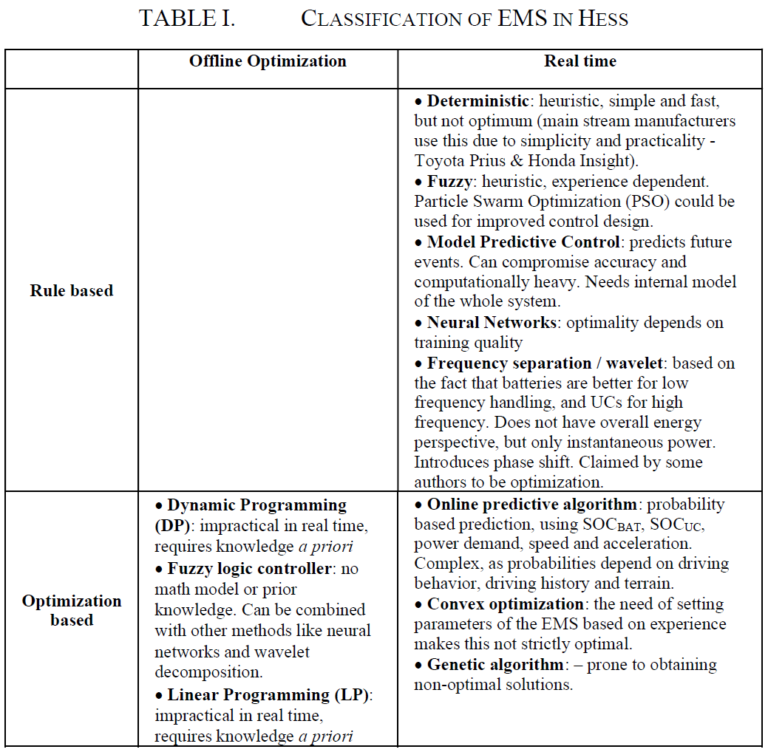
Compiling the various types of EMS declared in [1], [6], [7], [9], [10], [14], [16] and [26], they can roughly be divided as shown in Table I.
As it can be observed from all cited sources, classification is not standardized and can be interpreted from angles. In addition to the EMSs listed in Table I [1] and [3] name other EMS strategies like Reinforcement Learning, Simulated Annealing (SA) and Convex Programming. Reference [3] uses a different type of classification for EMSs.
B. Driving Cycles
Authors like [4], [6], [7], [10] and [16] claim algorithm complexity and driving cycle dependency are significant challenges in EMS design and optimization, and that most research is based on one single driving cycle, which is unrealistic. This will most probably stay a challenge indefinitely, as there is no way to actually predict all real life driving cycles.
Nevertheless, driving cycles are an essential input in majority of HESS EMS research and optimization. Designed mostly by government entities, they are intended to facilitate research concerning vehicular technology, and consist on datasets of speed versus time, under certain defined driving scenarios (urban, highway, traffic, etc.) [39]. Fig. 7 shows and example of the United State Government’s EPA Urban Dynamometer Driving Schedule (UDDS) [40].
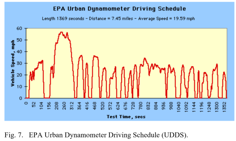
Some examples of the driving cycles used in the literature consulted in this paper are: EPA Urban Dynamometer Driving Schedule (UDDS) [6] [7] [14]; City II, ECE-15 and NEDC [21]; J1015 (Japan) and Indian Urban [14]; FTP and New York City Cycle (NYCC) [10] [15]; JC08 and HWFET [9], Manhattan Drive Cycle and US06 Drive Cycle [10]. Driving cycles are converted into data relevant for the specific research by translating the speed vs. time curves into power or current vs time curves, using mechanical, aerodynamic and electrical models of the vehicles under study.
C. Design and optimization
As mentioned before, there is a wealth of literature pertaining EMS design and optimization for HESS. Options range from design and functionality only research, with little or no regard for optimization, up to fully developed advanced optimization problems.
For example, [6] is a research case in which the optimization efforts, based on Genetic Algorithms, aim to minimize the size, cost, weight of the battery, as well as extended its life, while having the driving performance as a constraint, but the energy management per se is not subject to optimization, and the research uses a frequency (wavelet) separation approach as EMS. The work successfully manages to reduce battery aging in approximately 10%, at the end of the sample driving cycle (UDDS).
In contrast, the work in [21] uses a rule-based EMS to focus on extending the range of the vehicle under study, with no consideration for the sizing of the HESS. The paper states limitations of fuzzy logic, optimization or other rule based techniques (refer to Table I) like issues in high torque circumstances and low levels of SOCUC , and instead seeks to control the discharge of the UC and maximizing SOCUC, by means of maximum kinetic energy recovery during regenerative breaking. As a rule based approach, no optimization is guaranteed, but the authors claim a power consumption reduction of 32% and an increment in range of 48%, thanks to a maximized utilization of the kinetic energy during the sample driving cycle (City II).
Similarly, the work in [14] aims to increase battery life, by ruling that the UC bank deals with regeneration only (and not the battery), and both batteries and UC deliver power in the rest of the scenarios, all this by also regulating SOCUC and trying to match it with SOCBAT. The control system, despite being rule oriented, uses two stages of Artificial Neural Networks. As opposed to most studies, this case considers the maximum possible SOC of the HESS at the end of the driving cycles.
When compared to other benchmark studies considered (entirely rule based and fuzzy logic EMS), the proposed EMS in [14] outperforms such benchmarks at the end of several repetitions of the used driving cycles (J1015, Indian Urban and UDDS), regarding SOCUC, SOCBAT, losses and battery temperatures, suggesting under the support of experimental results that, even though not necessarily optimal, the proposal delivers superior results.
On the other hand, a fuzzy logic EMS is implemented in [7], together with a Multiple Input Controller in a concept car. The simulation part of the study uses the UDDS driving cycle. The main goal established by the authors is to control the SOCUC and smooth the battery power profile, to which it claims the battery life is extended by 55%. As in other cases, the proposed approach obtains benefits when compared to other benchmark EMSs, but cannot guarantee an optimized solution was achieved.
A special case of research is shown in [10]. The study evaluates two EMSs for real time implementation, aiming for current split optimization between batteries and UCs: one using Karush-Kuhn-Tucker (KKT) conditions, and another using neural networks. On the KKT case, optimization objectives are the minimization of the battery current, its variations, and the minimization of the UC versus a reference signal, aimed to maintain the UC energy above certain level as in other studies mentioned above. On the other hand, the neural network is trained using dynamic programing, to minimize power losses in the HESS, and reduce battery current fluctuations. Simulated results outperform the benchmark HEMS (battery only), in the sense that the battery current is smothered, in the most aggressive of the three used driving cycles. For such aggressive driving scenario, the neural network EMS defeats the KKT. Experimental results indicate that the KKT and neural network EMS reduce the decay of the SOH of the battery by 31% and 38% respectively.
V. Future research outlook and challenges
Expert reviews like [3] indicate that the benefit of a given HESS depends on many factors, and it is extremely difficult to meet all possible optimization and efficiency expectations in a single application. In this sense, the future of EMS and HESS research seems to point to the use of combined, multi factor and multi control EMS strategies to overcome this challenge.
On the other hand, the lack of standardized criteria to define HESS and EMS performance should be addressed by the scientific community in the future, to promote more organized efforts in this important field of electric mobility.
VI. References
[1] A. Demircali, P. Sergeant, S. Koroglu, S. Kesler and E. T. M. Ozturk, “Influence of the temperature on energy management in battery-ultracapacitor electric vehicles,” Journal of Cleaner Production, vol. 176, no. 1 March 2018, pp. 716 – 725, 2018.
[2] K. T. Chau, Electric Vehicle Machines and Drives, Singapore: Wiley – IEEE Press, 2015.
[3] R. Xiong, H. Chen, C. Wang and F. Sun, “Towards a smarter hybrid energy storage system based on battery and ultracapacitor – A critical review on topology and energy management,” Journal of Cleaner Production, vol. 202, no. November 20 2018, pp. 1228 – 1240, 2018.
[4] C. Zhao, H. Yin and C. Ma, “Quantitative Efficiency and Temperature Analysis of Battery-Ultracapacitor Hybrid Energy Storage Systems,” IEEE Transactions on Sustainable Energy, vol. 7, no. 4, pp. 1791 – 1802, 2016.
[5] P. Grbovic, Ultra-Capacitors in Power Conversion Systems – Aplications, Analysis and Design From Theory to Practice, West Sussex: Wiley – IEEE Press, 2014.
[6] L. Zhang, X. Hu, Z. Wang, F. Sun, J. Deng and D. Dorrell, “Multiobjective Optimal Sizing of Hybrid Energy Storage Sytem for Electric Vehicles,” IEEE Transactions on Vehicular Technology, vol. 67, no. 2, pp. 1027- 1035, 2018.
[7] F. Akar, Y. Tavlasoglu and B. Vural, “An Energy Management Strategy for a Concept Battery/Ultracapacitor Electric Vehicle With Improved Battery Life,” IEEE Transactions on Transportation Electrification, vol. 3, no. 1, pp. 191 – 200, 2017.
[8] S. Hu, Z. Liang and X. He, “Ultracapacitor-Batteru Hybrid Energy Storage System Based on the Asymmetric Bidirectional Z-Source topology for EV,” IEEE Transactions on Power Electronics, vol. 31, no. 11, pp. 7489 – 7498, 2016.
[9] H. Yin, W. Zhou, M. Li, C. Ma and C. Zhao, “An Adaptive Fuzzy Logic-Based Energy Management Strategy on Battery/Ultracapacitor Hybrid Electric Vehicles,” IEEE Transactions on Transportation Electrification, vol. 2, no. 3, pp. 300 – 311, 2016.
[10] J. Shen and A. Khaligh, “Design and Real-Time Controller Implementation for a Battery-Ultracapacitor Hybrid Energy Storage System,” IEEE Transactions on Industrial Informatics, vol. 12, no. 5, pp. 1910 – 1918, 2016.
[11] S. Hu, Z. Liang, D. Fan and X. He, “Hybrid Ultracapacitor-Battery Energy Storage Sytem Based on Quasi-Z-Source Topology and Enhanced Frequency Dividing Coordinated Control for EV,” IEEE Transactions on Power Electronics, vol. 31, no. 11, pp. 7598 – 7610, 2016.
[12] J. Kim and B. Cho, “State-of-Charge Estimation and State-of-Health Prediction of a Li-Ion Degraded Battery Based on an EKF Combined With a Per-Unit System,” IEEE Transactions on Vehicular Technology, vol. 60, no. 9, pp. 4249 – 4260, 2011.
[13] H. Chaoui, N. Golbon, I. Hmouz, R. Souissi and S. Tahar, “Lyapunov-Based Adaptive State of Charge and State of Health Estimation for Lithium-Ion Batteries,” IEEE Transactions on Industrial Electronics, vol. 62, no. 3, pp. 1610 – 1618, 2015.
[14] K. Alobeidli and V. Khadkikar, “A New Ultracapacitor State of Charge Control Concept to Enhance Battery Lifespan of Dual Storage Electric Vehicles,” IEEE Transactions on Vehicular Technology, vol. 67, no. 11, pp. 10470 – 10481, 2018.
[15] M. Masih-Tehrani and M. Dahmardeh, “A Novel power DIstribution System Employing State of Available Power Estimation for a Hybrid Energy Storage System,” IEEE Transactions on Industrial Electronics, vol. 65, no. 8, pp. 6676 – 6685, 2018.
[16] J. Shen and A. Khaligh, “A Supervisory Energy Management Control Strategy in a Battery/Ultracapacitor Hybrid Energy Storage System,” IEEE Transactions on Transportation Electrification, vol. 1, no. 3, pp. 223 – 231, 2015.
[17] MIT Electric Vehicle Team, “A Guide to Understanding Battery Specifications,” December 2008. [Online]. Available: http://web.mit.edu/evt/summary_battery_specifications.pdf. [Accessed 2 12 2018].
[18] M. Murnane and A. Ghazel, “A Closer Look at State of Charge (SOC) and State of Health (SOH) Estimation Techniques for Batteries,” 2017. [Online]. Available: https://www.analog.com/media/en/technical-documentation/technical-articles/A-Closer-Look-at-State-Of-Charge-and-State-Health-Estimation-Techniques-….pdf. [Accessed 2 12 2018].
[19] M. Gholizadeh and F. Salmasi, “Estimation of State of Charge, Unknown Nonlinearities, and State of Health of a Lithium-Ion Battery Based on a Comprehensive Unobservable Model,” IEEE Transactions on Industrial Electronics, vol. 61, no. 3, pp. 1335 – 1344, 2014.
[20] H. He, X. R. X. Zhang, F. Sun and J. Fan, “State-of-Charge Estimation of the Lithium-Ion Battery Using an Adaptive Extended Kalman Filter Based on an Improved Thevenin Model,” IEEE Transactions on Vehicular Technology, vol. 60, no. 4, pp. 1461 – 1469, 2011.
[21] J. Armenta, C. Nuñez, N. Vasairo and I. Lazaro, “An advanced energy management system for controlling the ultracapacitor discharge and improving the electric vehicle range,” Journal of Power Sources, vol. 284, no. June 15th 2015, pp. 452-458, 2015.
[22] R. Kroeze and P. Krein, “Electrical Battery Model for Use in Dynamic Electric Vehicle Simulations,” in 2008 IEEE Power Electronics Specialists Conference, Rhodes, Greece, 2008.
[23] X. Gong, R. Xiong and C. Mi, “Study of the Characteristics of Battery Packs in Electric Vehicles With Parallel-Connected Lithium-Ion Battery Cells,” IEEE Transactions on Industry Applications, vol. 51, no. 2, pp. 1872 – 1879, 2015.
[24] M. Zheng, B. Qi and X. Du, “Dynamic model for characteristics of Li-ion battery on electric vehicle,” in 2009 4th IEEE Conference on Industrial Electronics and Applications, Xi’an, China, 2009.
[25] J. Jiang and C. Zhang, Fundamentals and Applications of Lithium-ion Batteries in Electric Drive Vehicles, Singapore: John Wiley & Sons, 2015.
[26] B. Hredzak, V. Agelidis and M. Jang, “A Model Predictive Control System for a Hybrid Battery-Ultracapacitor Power Source,” IEEE Transactions on Power Electronics, vol. 29, no. 3, pp. 1469 – 1479, 2014.
[27] I. Oukkacha, M. Camara and B. Dakyo, “Electric Vehicles Energy Management using Lithium-batteries and Ultracapacitors,” in 2017 Twelfth International Conference on Ecological Vehicles and Renewable Energies (EVER), Monte-Carlo, Monaco, 2017.
[28] M. Chen and G. Rincon-Mora, “Accurate electrical battery model capable of predicting runtime and I-V performance,” IEEE Transactions on Energy Conversion, vol. 21, no. 2, pp. 504 – 511, 2006.
[29] A. Ostadi and M. Kazerani, “A Comparative Analysis of Optimal Sizing of Battery-Only, Ultracapacitor-Only, and Battery–Ultracapacitor Hybrid Energy Storage Systems for a City Bus,” IEEE Transactions on Vehicular Technology, vol. 64, no. 10, pp. 4449 – 4460, 2015.
[30] l. Zubieta and R. Bonert, “Characterization of Double-Layer Capacitors for Power Electronics Applications,” IEEE Transactions on Industry Applications, vol. 36, no. 1, pp. 199 – 205, 2000.
[31] Y. Parvini, J. Siegel, A. Stefanopoulou and A. Vahidi, “Supercapacitor Electrical and Thermal Modeling, Identification, and Validation for a Wide RAnge of Temperature and Power Applications,” IEEE Transactions on Industrial Electronics, vol. 63, no. 3, pp. 1574 – 1584, 2016.
[32] T. Wei, X. Qi and Z. Qi, “An Improved Ultracapacitor Equivalent Circuit Model for the Design of Energy Storage Power Systems,” in 2007 International Conference on Electrical Machines and Systems (ICEMS), Seoul, South Korea, 2007.
[33] L. Shi and M. Crow, “Comparison of ultracapacitor electric circuit models,” in 2008 IEEE Power and Energy Society General Meeting – Conversion and Delivery of Electrical Energy in the 21st Century, Pittsburgh, PA, USA, 2008.
[34] M. Camara, H. Gualous and F. Gustin, “DC/DC Converter Design for Supercapacitor and Battery Power Management in Hybrid Vehicle Applications—Polynomial Control Strategy,” IEEE Transactions on Industrial Electronics, vol. 57, no. 2, pp. 587 – 597, 2010.
[35] R. Carter, A. Cruden and P. Hall, “Optimizing for Efficiency or Battery Life in a Battery/Supercapacitor Electric Vehicle,” IEEE Transactions on Vehicular Technology, vol. 61, no. 4, pp. 1526 – 1533, 2012.
[36] J. Blanes, R. Gutierrez, A. Garrigos, J. Lizan and J. Martinez Cuadrado, “Electric Vehicle Battery Life Extension Using Ultracapacitors and an FPGA Controlled Interleaved Buck–Boost Converter,” IEEE Transactions on Power Electroncis, vol. 28, no. 12, pp. 5940 – 5948, 2013.
[37] N. Mohan, T. Undeland and W. Robbins, Power Electronics Converters, Applications and Design, Hoboken, NJ: John Wiley & Sons, Inc, 2003.
[38] F. Zheng Peng, “Z-Source Inverter,” IEEE Transactions on Industry Applications, vol. 39, no. 2, pp. 504 – 510, 2003.
[39] S. Fui Tie and C. Wei Tan, “A review of energy sources and energy management systems in electric vehicles,” Renewable and Sustainable Energy Reviews, vol. 20, no. April 2013, pp. 82 – 102, 2013.
[40] United States Environmental Protection Agency, “EPA Urban Dynamometer Driving Schedule (UDDS),” 23 02 2017. [Online]. Available: https://www.epa.gov/emission-standards-reference-guide/epa-urban-dynamometer-driving-schedule-udds. [Accessed 06 12 2018].
Recommended citation.
Pineda, F., “State of Research of Battery and Ultracapacitor Based Hybrid Energy Storage Systems, Their Control and Optimization, for Application in Electric Vehicles”. Altus Dexter (www.altusdexter.com), December 2018

About the author
Fabian Pineda, P.E., is the Founder and Managing Director of Altus Dexter. He has extensive experience in project management, design, operation, reliability, and maintenance of electrical systems for industrial, oil, gas and offshore applications.
We also recommend
Electrical Reliability in Oil and Gas: A Study Case
In the high-stakes environment of oil and gas, electrical system reliability...
ReadCONTACT US
Get in touch with us. We offer complimentary consultations to our prospective clients. Feel free to fill out the form, call us or send us an e-mail.
- (832) 773-1194
- info@altusdexter.com